See how to use SAP HANA Cloud Integration (SAP HCI) to model the invocation of mappings in order to map fields between different message formats. You apply the mapping step in your integration flow and use the mapping editor to graphically assign fields of different message formats to each other.
Key Concept
SAP HANA Cloud Integration (SAP HCI) is SAP’s integration platform as a service (iPaaS) solution allowing you to build scenarios for connecting cloud applications with other cloud or on-premise applications. Those applications do not necessarily have to be SAP applications, but you especially benefit from SAP HCI if you connect SAP cloud/on-premise applications with each other because SAP ships predefined integration content for SAP HCI. This significantly reduces integration costs.
Every integration project requires mapping functionality due to the many different message formats that are being used in the systems that need to be connected. Hence, integration solutions such as SAP HANA Cloud Integration (SAP HCI) must provide functionality to solve this problem elegantly. This article shows how to apply mappings in your integration flows. I explain the configuration of the mapping step in great detail. In addition I show how SAP HCI message processing differs from message processing within SAP Process Integration (SAP PI) and what consequences this brings for the mapping’s configuration.
In every integration scenario, mapping between different data formats of the participating systems is always a hot topic. I would say it is one of the most important tasks you have to do for every integration project, and it always requires effort to implement. Supporting the modeler with a convenient mapping environment and a high-performing mapping engine is of highest importance for every integration framework.
SAP gained some experience in building a mapping engine through its SAP PI product. Right from the beginning, SAP PI included a Java-based mapping engine. Consequently it became an obvious choice to include the same mapping engine in SAP HCI as well. It is a stable and reliable engine that has been in productive use for many years. In addition, because of this mapping engine reuse, you can also reuse your SAP PI mappings in SAP HCI. This saves your investment in developed mapping logic.
This article, however, is not about the mapping engine itself, the functionality it provides, or how to solve certain mapping challenges because a plethora of material is already publicly available either in SAP’s online documentation for SAP PI or on SCN. Instead, I address the question of how to apply the mapping engine within SAP HCI so that you know how to use a mapping step in your message processing chain correctly.
This is of particular importance as SAP HCI is based on the Apache Camel integration framework, which can handle almost any message format—it is a payload-agnostic routing and mediation engine. Apache Camel doesn’t follow the interface concept as you know it from SAP PI, where you have to
precisely define XML-based inbound and outbound interfaces in the Enterprise Services Repository (ESR) before you can actually start modeling the integration scenario.
All the overhead of defining interfaces prior to modeling the integration is not necessary for SAP HCI. You can just push anything to SAP HCI and as long as you don’t need access to the actual payload (e.g., for routing purposes) SAP HCI forwards the message to receivers as is. However, the mapping engine has the same history as SAP PI with its XML background. Therefore, it works on XML transformations only. So a conversion to XML before invoking the mapping engine is mandatory in SAP HCI. As a consequence, you must provide the XML schema of the source and the target message by uploading respective XML Schema Definition (XSD) or Web Services Description Language (WSDL) files to SAP HCI. Let’s see how this looks in a concrete example.
The Scenario
For this article I continue from where I left off in my previous
SAP Professional Journal article, “
Invoking an OData Service with SAP HANA Cloud Integration.” In that other article you learned how to invoke an Open Data (OData) service for retrieving order details for a given order number. The scenario is shown in
Figure 1.

Figure 1
Invoke an OData service via a Request-Reply step
As part of the configuration of the OData connection to the receiver, the Query Editor was used to model the access to the OData source. The editor allows you to, for example, define the entities for which a query should search, the individual fields of the entity you are interested in, the filter criteria of the query, and the order-by condition for sorting the found entities accordingly.
One important part of configuring the connectivity to the OData service provider by the Query Editor is the automatic generation of an XSD file representing the return message of the service in XML format. (See the confirmation message in SAP HCI’s graphical modeling environment after finishing the configuration of the connection’s properties with the Query Editor in
Figure 2.)

Figure 2
Query Editor's confirmation message about the automatically created EDMX and XSD files
This happens even though an OData service typically returns its results in either JavaScript Object Notation (JSON) or Atom format. Obviously the Request-Reply step of
Figure 1 implicitly invokes a mapping from JSON/Atom to XML so that the message processing chain can continue working on XML in the forthcoming steps. However, what if the current format within the route is not in XML? In these cases you have to explicitly call a transformation step. As of December 2015, SAP HCI supports steps for converting comma separated values (CSV) and JSON to XML, and vice versa. In the web-based modeling environment of SAP HCI you find the respective converter beneath the message transformer’s icon

(
Figure 3).
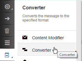
Figure 3
Pick a Converter step from the palette
My goal for the scenario above is now to map the returned entity into an XML format of my choice. The business scenario behind this assumption is that quite frequently data needs to be returned in a specific XML format to a consumer. You have to convert the automatically generated XML format of the Request-Reply step in your route to the target format the consumer expects.
Typically the required target format is either defined by an XSD or a WSDL file. If you have an SAP PI background you can also easily define those files using the Enterprise Service Builder—the tool SAP PI provides for designing interfaces in the ESR. Any other XML tool works as well. For my example I’ve created such an XML file (
Figure 4). Its name is GetOrderShipDetails_Sync.wsdl.
<?xml version="1.0" encoding="UTF-8" ?>
- <wsdl:definitions name="GetOrderShipDetails_Sync" targetNamespace="https://hci.sap.com/demo" xmlns:p1="https://hci.sap.com/demo" xmlns:wsp="https://schemas.xmlsoap.org/ws/2004/09/policy" xmlns:wsu="https://docs.oasis-open.org/wss/2004/01/oasis-200401-wss-wssecurity-utility-1.0.xsd" xmlns:wsdl="https://schemas.xmlsoap.org/wsdl/">
  <wsdl:documentation />
  <wsp:UsingPolicy wsdl:required="true" />
  <wsp:Policy wsu:Id="OP_GetOrderShipDetails_Sync" />
- <wsdl:types>
- <xsd:schema targetNamespace="https://hci.sap.com/demo" xmlns:xsd="https://www.w3.org/2001/XMLSchema" xmlns="https://hci.sap.com/demo">
  <xsd:element name="OrderNumber_MT" type="OrderNumber_DT" />
  <xsd:element name="OrderShippingDetails_MT" type="OrderShippingDetails_DT" />
- <xsd:complexType name="OrderNumber_DT">
- <xsd:sequence>
  <xsd:element name="orderNumber" type="xsd:string" />
  </xsd:sequence>
  </xsd:complexType>
- <xsd:complexType name="OrderShippingDetails_DT">
- <xsd:sequence>
  <xsd:element name="orderNumber" type="xsd:string" />
  <xsd:element name="customerName" type="xsd:string" />
  <xsd:element name="shipCity" type="xsd:string" />
  <xsd:element name="shipStreet" type="xsd:string" />
  <xsd:element name="shipPostalCode" type="xsd:string" />
  <xsd:element name="shipCountry" type="xsd:string" />
  <xsd:element name="shipDate" type="xsd:string" />
  </xsd:sequence>
  </xsd:complexType>
  </xsd:schema>
  </wsdl:types>
- <wsdl:message name="OrderNumber_MT">
  <wsdl:documentation />
  <wsdl:part name="OrderNumber_MT" element="p1:OrderNumber_MT" />
  </wsdl:message>
- <wsdl:message name="OrderShippingDetails_MT">
  <wsdl:documentation />
  <wsdl:part name="OrderShippingDetails_MT" element="p1:OrderShippingDetails_MT" />
  </wsdl:message>
- <wsdl:portType name="GetOrderShipDetails_Sync">
  <wsdl:documentation />
- <wsdl:operation name="GetOrderShipDetails_Sync">
  <wsdl:documentation />
- <wsp:Policy>
  <wsp:PolicyReference URI="#OP_GetOrderShipDetails_Sync" />
  </wsp:Policy>
  <wsdl:input message="p1:OrderNumber_MT" />
  <wsdl:output message="p1:OrderShippingDetails_MT" />
  </wsdl:operation>
  </wsdl:portType>
- <wsdl:binding name="GetOrderShipDetails_SyncBinding" type="p1:GetOrderShipDetails_Sync">
  <soap:binding style="document" transport="https://schemas.xmlsoap.org/soap/http" xmlns:soap="https://schemas.xmlsoap.org/wsdl/soap/" />
- <wsdl:operation name="GetOrderShipDetails_Sync">
  <soap:operation soapAction="https://sap.com/xi/WebService/soap1.1" xmlns:soap="https://schemas.xmlsoap.org/wsdl/soap/" />
- <wsdl:input>
  <soap:body use="literal" xmlns:soap="https://schemas.xmlsoap.org/wsdl/soap/" />
  </wsdl:input>
- <wsdl:output>
  <soap:body use="literal" xmlns:soap="https://schemas.xmlsoap.org/wsdl/soap/" />
  </wsdl:output>
  </wsdl:operation>
  </wsdl:binding>
  </wsdl:definitions>
Figure 4
The GetOrderShipDetails_Sync.wsdl file
To summarize: the source message for the mapping step is the structure defined in the automatically generated XSD file OrdersEntityGET0.xsd (compare
Figure 2) and the target message is the response part of the synchronous service interface described in GetOrderShipDetails_Sync.wsdl.
Applying the Mapping Step in the Message Processing Chain
To use the mapping engine in the route, you first have to position the mapping step in the integration flow pool. In the palette a dedicated mapping icon is available (Figure 5).

Figure 5
Select the Mapping step from the palette
Click it, move the mouse pointer (which changed to three parallel horizontal bars (
Figure 6) into the pool titled Integration Process, and click again. By this you have positioned the mapping step in your pool and the mapping editor opens immediately (
Figure 7).
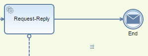
Figure 6
Positioning the Mapping step in the integration flow (mouse pointer changed to three horitzontal bars)
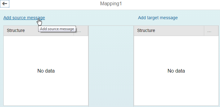
Figure 7
Mapping editor opens after positioning of the mapping task
Obviously both the source and the target messages are missing. Next I describe how to use either a pre-generated XSD file or a self-developed WSDL file for the definition of source and target messages. I start with the assignment of the source message. Click the Add source message link in
Figure 7. This opens the Select target message dialog shown in
Figure 8.

Figure 8
Dialog for selecting the target message
The dialog lists all the files that have either already been generated or uploaded from the file system. In my example only the file that has been automatically generated by the Query Editor is listed. You know from the summary of the last paragraph that OrdersEntityGET0.xsd is the file describing the source message. Click it once. You immediately return to the mapping editor, which shows the structure of the source message on the left side of the screen (
Figure 9).

Figure 9
Mapping editor displaying the structure of the source message after assigning the XSD file
Next you assign the target message by clicking the Add target message link in the upper right corner of the mapping editor. Again the dialog for assigning the appropriate file opens (
Figure 10).

Figure 10
Explicit upload of a file from the file system containing the description of the target message's structure
As the file containing the target message’s structure isn’t available yet, you explicitly pick it from the local file system. For this click the Upload from File System link in the lower left corner of the Select target message dialog. The standard Open file dialog opens (
Figure 11).
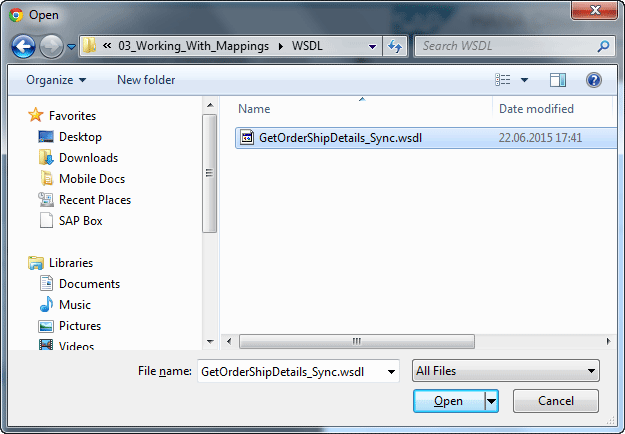
Figure 11
Pick either a WSDL or XSD file from the file system
Navigate to the folder containing the GetOrderShipDetails_Sync.wsdl file and click the Open button. As already mentioned, only WSDL or XSD files are allowed for defining the message’s structure. As the WSDL file contains the description of a synchronous interface, another dialog for selecting an element opens (
Figure 12).

Figure 12
Select the correct target structure from a synchronous interface
Why is this the case? The answer to this question is pretty straightforward: synchronous interfaces consist of two parts, a request part and a response part. Typically these are two completely different structures.
Just take my scenario as an example: I am retrieving details for an order based on an order number coming in via the request message. So the request message contains just one field: the order number. The response message, on the contrary, contains the details of the order. Hence, it comprises a bunch of fields. This is exactly what you see in
Figure 12. The first entry named OrderNumber_MT reflects the request message containing just the order number as the only field. The second entry, OrderShippingDetails_MT, stands for the response message and contains all the details that make up the order.
On a side note: SAP PI specialists will recognize the so-called message types (MT) postfix (the string MT after the data type’s name) for both elements. It is a typical habit to name the message type this way if you create message types in the ESR. And, yes, I’ve created the synchronous interface in the ESR. So the interoperability between SAP PI and SAP HCI on a data level is ensured.
Obviously you have to pick the second entry from the list as your target message structure. Click it once and the user interface (UI) immediately returns to the mapping editor. The mapping editor analyzes the structure of the response message and depicts it accordingly.
Figure 13 shows the result on the right side of the screen.
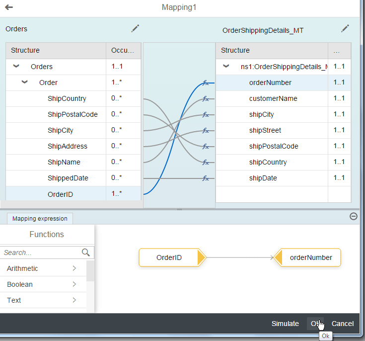
Figure 13
The mapping editor after opening both structures and after finishing of the mapping exercise
The mapping editor itself should look familiar to those who have worked with SAP PI before. You can now assign field mappings by simply dragging and dropping source fields from the left to the corresponding target fields on the right. I did this for my simple scenario and the result is also depicted in
Figure 13.
You can also benefit from several predefined functions that are shipped with the mapping editor and that are listed in the Functions area of
Figure 13. As I’ve explained already, you will find tons of material on SCN and in the SAP PI online help when it comes to more complex mappings. You will find the handling of the graphical mapper quite intuitive and convenient. It shouldn’t be a problem to define the mapping between the two structures as it is shown in the figure.
Also notice the Simulate button in the lower right corner of the mapping editor. You can immediately check your mapping for correctness by uploading an example message to the mapping editor, which, in turn, runs your mapping and displays the result. This results in short turnaround cycles between development and test.
Once you are done with your mappings, click the Ok button (also located in the lower right corner of the mapping editor) and you are back in the UI for modeling your integration flow. Your mapping step is selected in the process model and in the properties area beneath the process diagram you will just see the name of your mapping (
Figure 14).

Figure 14
Properties of the mapping step
I recommend that you give your mapping a self-explanatory name as the default name Mapping1 isn’t that useful. Just click the Rename button and provide a new name. Your change is confirmed by the system with an appropriate confirmation message (
Figure 15).

Figure 15
Confirmation message after renaming the mapping
Finally, drag the mapping step on the arrow connecting the Request-Reply step with the message-end event in
Figure 1 to actually position the mapping activity between the two. The final result of your process model is shown in
Figure 16.
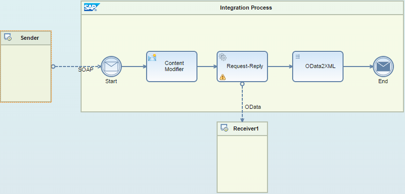
Figure 16
The final result of the process model after positioning the mapping step before the End event
That’s it! You have finished the configuration of the mapping activity and can now run your new integration flow. As I’ve explained in my other articles, use a Simple Object Access Protocol (SOAP) tool of your choice (e.g., SoapUI) and invoke your solution. An appropriate request message might look like the one depicted in
Figure 17.
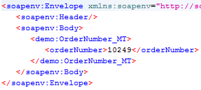
Figure 17
Example message
After passing the integration flow, the result message should look similar to the one shown in
Figure 18.

Figure 18
Reply message after successful invocation of the integration flow including the mapping step
Mappings are an important aspect in every integration project. SAP HCI benefits from a mapping engine originally developed for SAP PI. You have learned how the mapping engine is integrated into SAP HCI, and how you can invoke it in your integration flows by applying the mapping activity. You have also seen how the message processing differs from SAP PI (keyword: payload-agnostic behavior in SAP HCI) and that this difference requires the explicit definition of message structures by either using XSD or WSDL files for configuring the mapping step. With this knowledge, together with the other two articles of the SAP HCI series, you are now well equipped to tackle even more sophisticated integration challenges.

Dr. Volker Stiehl
Prof. Dr. Volker Stiehl studied computer science at the Friedrich-Alexander-University of Erlangen-Nuremberg. After 12 years as a developer and senior system architect at Siemens, he joined SAP in 2004. As chief product expert, Volker was responsible for the success of the products SAP Process Orchestration, SAP Process Integration, and SAP HANA Cloud Integration (now SAP HANA Cloud Platform, integration service). He left SAP in 2016 and accepted a position as professor at the Ingolstadt Technical University of Applied Sciences where he is currently teaching business information systems. In September 2011, Volker received his Ph.D. degree from the University of Technology Darmstadt. His thesis was on the systematic design and implementation of applications using BPMN. Volker is also the author of Process-Driven Applications with BPMN as well as the co-author of SAP HANA Cloud Integration and a regular speaker at various national and international conferences.
You may contact the author at
editor@SAPpro.com.
If you have comments about this article or publication, or would like to submit an article idea, please contact the
editor.


