Software architects and developers involved in service-oriented architecture projects can use the Enterprise Services Repository to design integration content following a top-down approach. This approach facilitates your design work because you have an overview of the content objects that belong to your integration scenarios as well as how these objects are related to each other. Keeping your design work and the created content transparent and interlinked saves you time and effort.
Key Concept
Enterprise Services Repository, included in SAP NetWeaver Process Integration 7.1 (SAP NetWeaver PI 7.1), provides an enhanced modeling environment that improves the top-down design capabilities available in releases prior to SAP NetWeaver PI 7.1. The integrated modeling environment enables users to design integration content starting with a model and then they can add the relevant interfaces and data types.
Today’s business processes span several departments and can even involve external business partners. In addition to that, the speed of change has increased considerably: Companies have to be able to quickly adapt their business processes to new business requirements. As a result, modeling and design challenges arise. Furthermore, as large business processes typically are implemented on extensive and complex system landscapes, there’s a demand for a modeling environment that allows you to concentrate on the business process without the need to care for the technical implementation level.
The Enterprise Services Repository (ES Repository) provides a modeling and design environment that allows you to design collaborative processes — particularly the integration-relevant aspects, such as mappings of data structures — on an abstract level first. This is independent from the technical level of the system landscape in which you plan to implement the process.
The decoupling of the business level from the technical implementation level provides the flexibility for the solution architect to change a business process according to new business requirements (e.g., adding a new field to a data type) without having to worry about the implications the change might have on the technical implementation level, such as the individual connections between the involved systems.
The ES Repository allows you to design integration content top-down. In this process, you start with a model and then, based on the model, specify the other integration content types, such as service interfaces and mappings. I will introduce the basic concepts that establish the ES Repository as an environment for the top-down design of integration content. SAP NetWeaver PI 7.1 has two new model types available that you can use as a starting point to design integration content: the process integration scenario model and the process components interaction model. The modeling environment is interlinked with editors for other integration content types, such as service interfaces and mappings. To perform the steps I describe, you need SAP NetWeaver PI 7.1 or SAP enhancement package 1 for SAP NetWeaver PI 7.1.
Process Models for Integration
Two new model types — the integration scenario model and the process components interaction model — available in ES Repository describe the integration-relevant aspects of collaborative business processes. The basic element used in these models is the process component. A process component is a part of the value chain of a collaborative business process. If you assume the business process spans different departments of one company, then a process component represents one part of the process that is performed in one department. For example, one process component covers all the steps that are relevant for the processing of sales orders. It may interact with another process component in a different department that covers all steps relevant for invoice processing.
Integration Scenario Model
An integration scenario model shows the process components that are involved in a collaborative process, as well as the connections between them. This model also includes deployment units, which group process components that you need to install together on one system at configuration time. The process components as modeled in an integration scenario model are nothing more than black boxes with no inner structure specified. Basically, an integration scenario shows the bird’s eye view of the integration. Figure 1 shows an integration scenario model with the corresponding element types.

Figure 1
Integration scenario model showing different process components interconnected with each other
The integration scenario model contains five different process components interacting with each other. The process components in blue represent those process components that belong to your company or business. The process component in gray represents a process component of a business partner that is connected by B2B communication with one of your own businesses. You can specify which of your process components run on the same, or different, deployment units.
Two process components running on the same deployment unit can interact directly with each other. This kind of interaction is denoted by a green arrow. The interactions of process components from different deployment units in general are described by service interfaces designed in the ES Repository. These kinds of interaction are typical candidates for the use of SAP NetWeaver PI as integration middleware. In the integration scenario model, these interaction types are denoted by a dark blue arrow.
Process Components Interaction Model
To specify the interaction between two process components in detail, you use a process components interaction model. This model contains the details of one connection in an integration scenario. In particular, a process components interaction model allows you to model the following entities:
- Process component: represents one part of the value chain of a business application or a business process
- Service interface: represents a set of functions that is either provided by an application (e.g., inbound service interface) or used by an application (e.g., outbound service interface)
- Service interface operation: represents the smallest, separately callable function, described by a set of data types used as input, output, and fault parameters serving as a signature
- Message type: defines the root element of a message
- Operation mapping: assigns a mapping program for a pair of service interface operations
- Communication channel template: contains the preconfiguration of a communication channel that you can specify at design time in the ES Repository
Figure 2 shows how both model types relate to each other.

Figure 2
The relationship between the integration scenario and the process components interaction model
Note
For details on the concept behind each of these object types, see the documentation in SAP Help at
https://help.sap.com/. Follow menu path SAP NetWeaver PI 7.1 > SAP NetWeaver Process Integration Library > Function-Oriented View > Process Integration > ES Repository.
Whereas an integration scenario model shows the high-level view of the integration of different process components, a process components interaction model shows the details of one interaction between two process components. When you click a connection in an integration scenario model, you can open the corresponding process components interaction model for this connection. Although the integration scenario model shows no details of the process components and the connections between them, a process components interaction model displays details such as which interfaces or mappings are used by the process components to interact with each other.
Note
Integration developers focus more on how process components interact with each other rather than how the business logic represented by a process component is implemented in detail. Accordingly, a process components interaction model shows only the integration-relevant aspects of two process components interacting with each other.
In a process components interaction model, you first model these entities as graphical (modeled) objects. A key feature of the modeling environment is that it is integrated within the ES Repository in such a way that you can create assignments from a modeled object to a corresponding object in the ES Repository. For example, starting from a modeled service interface, you can either directly create the needed service interface (if it doesn’t exist yet), or you can create an assignment to an existing service interface. In both cases, you can seamlessly navigate to the service interface editor and continue specifying the attributes of the service interface. Figure 3 shows a process components interaction model with the available modeling objects that you can assign to corresponding objects in the ES Repository.

Figure 3
Assignable modeling objects in a process components interaction model
The process components communicate with each other via service interface operations, and the data between the process components is exchanged with messages. The structure of a message is defined by message types. As in collaborative processes, the message structure of the outbound message (sent by the sender process component) might differ from the structure of the inbound message (what the receiver process component expects), so there has to be mapping to define the transformation between both. You can define communication channel templates to provide more details of the message exchange. With a communication channel template, you can define which adapter type is used to accomplish the communication at sender and receiver side technically. An adapter type can be the IDoc or the RFC adapter, for example.
Design Integration Content Based on a Model
The basic steps for designing integration content start with a process components interaction model. I created a simple example model to keep the focus on the general aspects of the modeling environment and on the technical concepts of SAP NetWeaver PI, rather than on particular business details. Technically, the model and its assigned integration content objects comprise a simple file-to-file transfer using SAP NetWeaver PI as integration middleware. After you have finished the procedure described in this article, you can use the model as a configuration template to set up and execute this basic communication scenario quickly and with a minimum amount of effort (model-based configuration).
Note
Using the model configurator with the process components interaction model is possible as of release enhancement package 1 for SAP NetWeaver PI 7.1.
Start the ES Repository and Create a Process Model
A prerequisite for the following steps is to create a software component version in the System Landscape Directory (SLD). The software component version should be based on SAP Basis 7.10. In SLD, choose MetaDataRequest as the Context. Import the new software component version to the ES Repository and define a namespace.
Step 1. Start the ES Repository. You start the ES Repository from the SAP NetWeaver PI start page, which is either accessible via transaction SXMB_IFR or via https://[hostname]:[port]/dir. For the Application Profile, choose Process Integration.
Step 2. Open the new software component version. In the navigation area of the ES Repository, position the cursor on the software component version, right-click, and choose New. Then choose Modeling > Model. For the Model Type, select SAP ProComp interaction model.
Step 3. Specify a name for the model and choose Create to open the modeling environment. In the graphical editor, on the left side of the graphical work area, you can choose among several icons, each representing another modeling entity. Click the process component icon  and then click the graphical work area to add the process component (Figure 4).
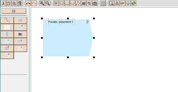
Figure 4
Add the process component in the interactive graphical work area
Continue building the model by adding the entities shown in Figure 5. In particular, do the following:
- Model two process components and name them ProcessComponent1 and ProcessComponent2
- Model two service interfaces and name them PersonalData_Out and PersonalData_In
- For each service interface, add an operation with the same name as the service interface
- Between the process components, add two message types (PersonalData1 and PersonalData2), as well as an operation mapping (PersonalData1_PersonalData2)
- Connect the operations, message types, and mapping
- Add two communication channel templates (SenderFileAdapter and ReceiverFileAdapter) and connect them with the service interfaces
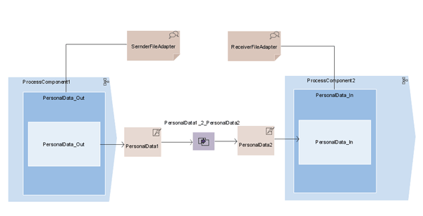
Figure 5
The completed process components interaction model
Step 4. Save the model by clicking the save icon. Note that I did not model any business objects for this simple scenario because it doesn’t comprise any complex business background.
Assign ESR Objects
In these steps, you link the modeled objects with their corresponding objects (i.e., ESR objects) in the ES Repository.
Note
In this process, you define a dependency between the software component version (where you build your content) and the SAP Basis 7.10 software component version. This allows you to reuse objects contained in the latter.
Assign Process Components
First, create assignments for the process components. Position the cursor on the left process component. Right-click and select Process Component Assignment > Create Assignment. In the following dialog, choose the namespace you have defined for the new software component version. Click the Save button. Repeat these steps for the right process component.
The assignment icon points out that for the corresponding modeling element, an object is defined in the ES Repository. By double-clicking this icon, you can navigate from the model to the corresponding message type object in the ES Repository.
Assign and Specify Interface Objects
Next, you create assignments for the service interfaces and create the corresponding ESR objects. Then you specify the service interfaces and assign message types to the service interfaces.
Step 1. Position the cursor on the service interface in the left process component. Right-click and select Service Interface Assignment > Create Assignment (Figure 6).
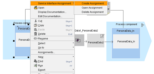
Figure 6
Create an assignment to a service interface
Step 2. In the next dialog, choose the namespace you specified for the new software component version and click the Save button.
Step 3. Position the cursor on the service interface in the left process component. Right-click and select Service Interface Assignment > Open Assignment. The system asks you if it should create the object PersonalData_Out. Click Create to confirm. This opens the service interface editor (Figure 7).
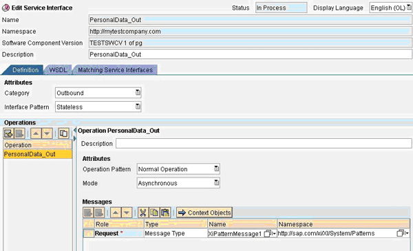
Figure 7
Service interface editor opened from the corresponding entity in the model
Step 4. Save the service interface by clicking the save icon. The service interface object is now displayed in the navigation area of the ES Repository (under > Service Interfaces).
Step 5. Continue specifying the service interface by selecting a message type (for the one operation it contains). For this example, select XIPatternMessage1 (input help) as the message type. The XIPatternMessage1 message type, located in software component version SAP Basis 7.10, is part of SAP’s predefined integration content, which is available for demo purposes. By using this message type, you do not have to define the message type and the used data type. Instead, you can use the message type and data type predefined by SAP.
Step 6. Save the service interface by clicking the save icon. Repeat the steps for the service interface on the right side. When assigning a message type to the service interface, choose XIPatternMessage2.
Assign Mapping Objects and Communication Channel Templates
With the following steps, you assign and specify the relevant mapping objects and communication channel templates. The necessary message mapping and communication channel templates are also already predefined by SAP and can be reused.
Step 1. Proceed as described in step 1 in the previous section for the service interfaces. However, position the cursor on the operation mapping to start with the assignment.
Step 2. Create the operation mapping with the suggested name: PersonalData1_PersonalData2.
Step 3. Save the operation mapping and assign a message mapping to it.
Step 4. Select the existing message mapping XiPatternMessage1ToMessage2 (input help). The needed message mapping XiPatternMessage1ToMessage2 is also predefined in the software component version SAP Basis 7.10.
Step 5. Save the operation mapping.
Finally, you specify the modeled communication channel templates.
Step 1. Position the cursor on the communication channel template modeled for the sender process component. Right-click and choose Communication Channel Template Assignment > Create Assignment.
Step 2. In the Create Assignment dialog, click the input help icon next to the Name field. Select the predefined communication channel template XiPatternChannel_FileSender.
Step 3. In the same way, for the receiver communication channel template assign the predefined communication channel template XiPatternChannel_FileReceiver.
Step 4. Save the model and activate all the ESR objects that were created. In the Change Lists tab, click the model and select Activate from the context menu.
You have modeled the interaction between two process components for a simple scenario. Additionally, the relevant service interfaces, data types, mapping objects, and communication channel templates are specified.
Peter Gutsche
Peter Gutsche joined SAP in 1999 with a university degree in physics. As an expert in the topic area of SOA middleware, he is responsible for writing product documentation about SAP NetWeaver Process Integration.
You may contact the author at peter.gutsche@sap.com.
If you have comments about this article or publication, or would like to submit an article idea, please contact the editor.


 and then click the graphical work area to add the process component (Figure 4).


