Learn the process flow for automating the extraction of data from a planning area to backup cubes via a process chain in an SAP Advanced Planning and Optimization (SAP APO) database. This is an extension of the SCM Expert article “How to Carry Out Data Extraction from a Planning Area in SAP APO.” Follow a step-by-step procedure to understand the prerequisites, importance, and configuration steps with the help of an example case study.
Key Concept
Demand Planning in SAP Advanced Planning and Optimization (SAP APO) helps to generate forecasts based on historical values. A planning area is one of the most important functions in SAP APO. A planning area is where most of the planning activities take place. A planning area groups together both characteristics and key figures under a single domain. Characteristics are master data fields that have specific values defined for business (for example, a product name). Key figures are transactional data fields that usually refer to a quantity or numeric value (for example, an amount). Planning area data resides within liveCache, a database that resides in memory and is used to speed up planning and processing capabilities within SAP APO. InfoCubes are central, multidimensional data models that are used for data backup and reporting purposes in an SAP system. By extracting the data, the system saves forecast data in a backup cube and it can be further used for reporting purposes. Process chains, as the name implies, are a sequence of chained processes with each of the processes carrying out a specific task in the given context.
Demand Planning (DP) within SAP Advanced Planning and Optimization (SAP APO) helps to generate forecasts based on historical values. A planning area is one of the most important functions in both DP and Supply Network Planning (SNP). It defines the area in which most of the planning activities take place, grouping together both characteristics and key figures under a single domain. To maintain data consistency and to avoid loss of data, it is generally a good practice to back up the data in the planning area to an InfoCube.
SAP APO does not need a separate SAP Business Warehouse (SAP BW) instance as it is built on top of SAP BW technology and uses many SAP BW objects, such as InfoObjects and InfoCubes. Although SAP APO is a separate information warehouse that is needed to support the planning process, planning data can be saved in SAP BW objects such as InfoCubes for better reporting.
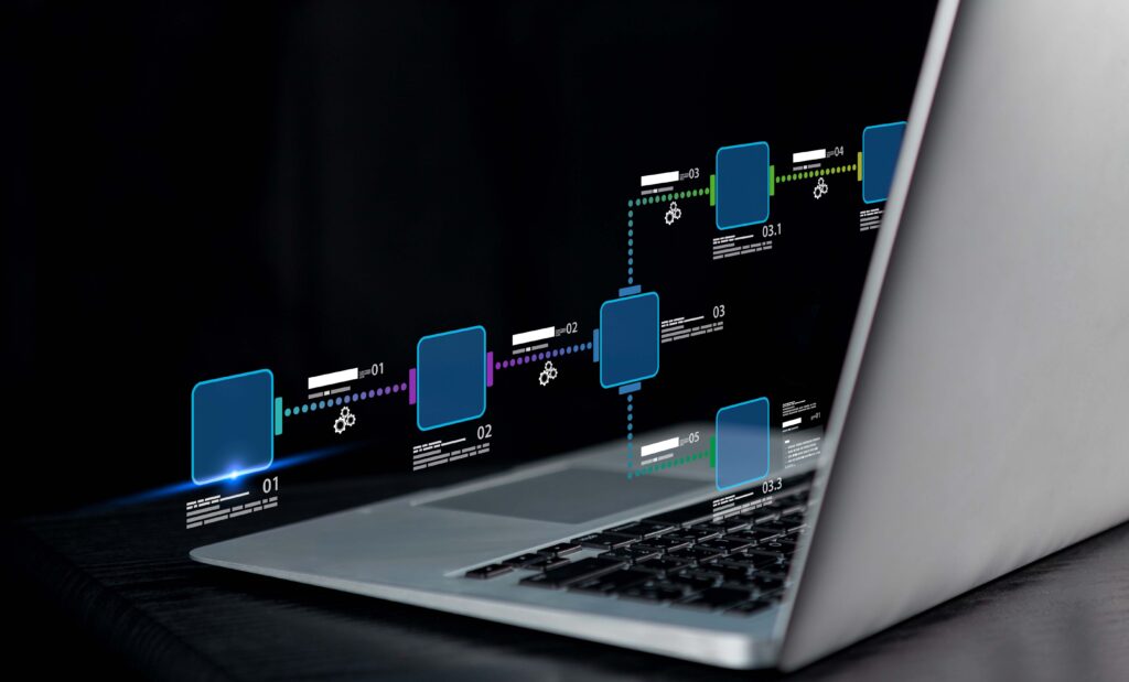
Figure 1 shows the extraction steps involved in loading the data from a planning area to the backup cube.

Figure 1
Data flow of extraction steps
Business Scenario
Consider an example of an automobile manufacturer that makes cars with various models. Historical sales data is used to carry out forecasting with different statistical forecasting models to develop the baseline forecast. The forecast is carried out at different regions, and these regions are then consolidated at the global level. This forecast is then released from DP to SNP to carry out multilevel and downstream planning. As part of a monthly sales and operations planning (S&OP) process, sales regions, field teams, marketing, finance, and operations share knowledge to improve forecasts through collaborative forecast development.
As part of the DP setup, the following objects are used as characteristics to carry out the monthly S&OP process:
- APO product
- APO location
- Region
- Country/market
- Territory
- Brand
- Model year
- Forecast type
- Customer
Prerequisite Objects to Extract Data from a Planning Area in DP
In this section I describe a list of objects that would be used in the process chain to automate the entire process of data extraction. To learn how these are configured and created, refer to the first article, “How to Carry Out Data Extraction from a Planning Area in SAP APO.” The objects are:
- Backup cube
- Data source
- Transformation
- Data transfer process
- InfoPackage
To view the contents of the backup cube, execute transaction code LISTCUBE. In the main screen that appears (Figure 2), enter the name of the cube (ZPA_BACK) in the InfoProvider field and click the execute icon.
Figure 2
Enter the name of the cube in the InfoProvider field
In the next screen, select 000 as the parameter in the APO Planning Version field to show the cube contents with this selection and then click the execute icon as shown in Figure 3.
Figure 3
Select a parameter in the APO Planning Version field
In next screen (Figure 4), you can view the cube contents.
Figure 4
LISTCUBE output
To view the data source, transformation, data transfer process, and InfoPackage objects, execute transaction code RSA1. In the screen the system displays, click the Find link to search for these objects as shown in Figure 5.
Figure 5
All BW objects needed to create a process chain
Process Chain Overview
Process chains provide a drag-and-drop interface that can be used for all background tasks that occur in SAP BW. This interface helps you visualize linked processes graphically, automate a series of steps in SAP BW, and centrally monitor and control tasks. To maintain a process chain, use transaction code RSPC.
Three major views (planning, checking, and log) are available within the process chain. They are used for different purposes. A planning view is used to create the process chains and provide different drag-and-drop interfaces. A checking view is used to check if a process chain is complete and ready to be used or if it contains any technical errors. A log view is used to view the process chain logs when the chain was ran.
These three views are represented by three different icons. After you execute transaction code RSPC, you can access the three different views (planning, checking, and log) by clicking one of the three icons highlighted in Figure 6. (The planning view, checking view, and log view icons are displayed from left to right in the menu bar.)
Figure 6
Process chain views
Process Chain Creation
To create the process chain, you first need to create the different individual components and then join them sequentially.
Note
Creating these objects is a transportable change, which means that system asks for a transport when you create each object. Save all the objects in a single transport that can then be imported from the development to the production system as per the business landscape.
First, you need to complete these two steps.
Step 1. Create a Display Component
Before creating the process chain, you need to create a display component. A display component is a grouping folder in which different process chains can be grouped under a single display component.
To create the display component, execute transaction code RSPC. In the main screen that appears, right-click the Process Chains text and select Create Display Component as shown in Figure 7.
Figure 7
Select the Create Display Component
In the refreshed screen, enter the name of the component in the Application comp. (component) field and a description in the Long description field as shown in Figure 8. After you populate these fields, click the enter icon.
Figure 8
Display the component name and a description
Step 2. Create a Process Chain
To create the process chain, right-click the display component (Test Component) created in step 1 and select Create Process Chain from the drop-down list of options shown in Figure 9.
Figure 9
Create a process chain
In the pop-up screen that the system displays, populate the Process Chain and Long description fields and then click the enter icon as shown in Figure 10.
Figure 10
Enter the process chain name and a description
Now there are different process steps under the process chain that need to be created.
Create a Start Process Variant
After you click the enter icon in Figure 10, a pop-up screen appears that asks you to insert a start process variant. Click the create icon and then click the enter icon as shown in Figure 11.
Figure 11
Insert a start process variant
In the next pop-up screen, enter the name of the start process variant and a description in the Process Variants and Long description fields, respectively, and then click the enter icon as shown in Figure 12.
Figure 12
Enter a start process variant name and description
In the Scheduling Options section of the next screen, note that there are two options through which a chain can be triggered (Direct Scheduling, where the chain can be triggered directly via transaction code RSPC, or Start Using Meta Chain or API, where the process chain can be triggered via a scheduling system such as Control-M. For my example, select the Direct Scheduling option and then click the Change Selections button as shown in Figure 13.
Figure 13
Start process variant parameters
In the next screen, click the Immediate button and then click the Check button and save icon as shown in Figure 14. This action ensures that the chain will start whenever it is executed.
Figure 14
Start process variant scheduling parameters
After you click the Check button and save icon, the system creates the Start Variant as shown on the right side of Figure 15.
Figure 15
Start variant created
Delete the Old Request from the Persistent Staging Area (PSA)
As shown in Figure 1, you see that data from the planning area is first extracted to the PSA. You need to delete old data from the PSA before loading a new one.
In Figure 15, expand the Other BW Processes node, select the Deletion of Requests from PSA component as shown in Figure 16 and drag it to the right side.

Figure 16
Drag the Deletion of Requests from PSA component to the right side of the screen
After you drag the Deletion of Requests from PSA component to the right side of Figure 16, a pop-up screen appears (Figure 17). Click the create icon.
Figure 17
Click the create icon to create the Deletion of Requests from PSA object
In the refreshed screen, enter a name in the Process Variants field and a description in the Long description field. After you populate these fields, click the enter icon as shown in Figure 18.
Figure 18
Enter a name for the process variant and a description
In the next screen (Figure 19), enter the name of the data source that was created in the first part of the article (e.g., ZPA) in the field under the DataSource column. In the field under the Src.system (source system) column, enter the name of the source system. The source system is the name of the client used by the user. In the field under the Older Than… column enter a value for which request should be deleted. For my example, enter a value of 0, which means that all old requests in the PSA would be deleted every time the chain is run. After entering the details, click the save icon.
Figure 19
Enter parameters to delete requests from the PSA
This action creates the object as shown in the right side of Figure 20.

Figure 20
Create the Delete Active PSA Request object
Load Data
This step is the InfoPackage step that is used to load the data from the data source to the PSA.
In Figure 20, expand the Load Process and Postprocessing node and select the Execute InfoPackage component as shown in Figure 21 and drag it to the right side of the screen.

Figure 21
Select the Execute InfoPackage component and drag it to the right side of the screen
After you drag the Execute InfoPackage component to the right side of Figure 21, a pop-up screen appears (Figure 22). Click the Load Data field and select the name of the InfoPackage created in step 6. of “How to Carry Out Data Extraction from a Planning Area in SAP APO” from the drop-down list of options and enter a description (e.g., ZINFOP) in the Description field. After you populate these fields, click the enter icon as shown in Figure 22.
Figure 22
Select an InfoPackage
In the pop-up screen that appears, enter F (full extraction) in the Extraction Mode field and CUBE in the Target Object Type field (you are loading data to a backup cube) and then click the execute icon as shown in Figure 23. (Note that the other fields in Figure 23 are auto-populated.)
Figure 23
Enter parameters to execute the InfoPackage
This action creates the object shown on the right side of Figure 24.
Figure 24
Create the Execute InfoPackage
Delete Index
Indexes are data-structure-sorted values containing a pointer to records in a table.
Indexes are used to improve data reading performance. Indexes are deleted or dropped during the data loading to data target and created again after the loading is finished.
In the same screen as Figure 24, expand the Data Target Administration node, select the Delete Index component (Figure 25), and drag it to the right side of the screen.
Figure 25
Select the Delete Index component and drag it to the right side of the screen
After you drag the Delete Index component to the right side of Figure 25, a pop-up screen appears (Figure 26). Click the create icon.

Figure 26
Click the create icon in the InsertDelete Index screen
In the refreshed screen, enter a name in the Process Variants field and a description in the Long description field. Click the enter icon as shown in Figure 27.
Figure 27
Enter the name of the Delete Index object and a description
In the refreshed screen, select the InfoCube where data is being saved (i.e., ZPA_BACK shown in "Step 1. Create a Display Component") and then click the save icon shown in Figure 28.

Figure 28
Enter parameters for the Delete Index object
In the next screen (Figure 29), you can see that system has created the Delete Index and also auto-generated the Create Index process.

Figure 29
The Delete Index and Create Index
Now, as shown in Figure 29, you can see that Delete Index is tied to the next step Create Index by a Connector. However, you don’t want the index to be created immediately after deletion. After deletion, you first need to load the data in the InfoCube via the data transfer process and then create the index. So, you need to remove the connector link between Deletion and Creation. To delete the link, right-click the connector and click the Remove Link option as shown in Figure 30.
Figure 30
Remove the link
In the refreshed screen, the connector is removed as shown in Figure 31.
Figure 31
The link between the Delete Index and the Create Index is removed
Data Transfer Process
This step is used to transfer the data from the PSA to an InfoCube.
In the screen shown in Figure 29, expand the Load Process and Postprocessing node and select the Data Transfer Process component as shown in Figure 32 and drag it to the right side of the screen.

Figure 32
Select the Data Transfer Process component and drag it to the right side of the screen
After you drag the Data Transfer Process component to the right side of Figure 32, a pop-up screen appears (Figure 33). In the Data Transfer Proc. field, select the data transfer process that was created in first part of the article (see Figure 32 in “How to Carry Out Data Extraction from a Planning Area in SAP APO”) from the drop-down list of options and enter a description in the Description field. After you enter your data, click the enter icon.
Figure 33
Select a data transfer process to create
This action creates the object shown on the right side of Figure 34.

Figure 34
The DTP object is created
Delete the Existing Request from the InfoCube
This step is used to delete the existing requests from the Infocube so that data is not overlapped.
In the screen shown in Figure 34, expand the Load Process and Postprocessing node and select the Delete Overlapping Requests from InfoCube component as shown in Figure 35 and drag it to the right side of the screen.

Figure 35
Select the Delete Overlapping Requests from InfoCube component and drag it to the right side of the screen
This action displays the pop-up screen in which you click the create icon (Figure 36).
Figure 36
Click the create icon to create a Delete Overlapping Requests from InfoCube object
In the refreshed screen (Figure 37), enter a name and description in the Process Variants and Long description fields, respectively, and then click the enter icon.
Figure 37
Enter a name and a description for the Delete Overlapping Requests from InfoCube object
In the next screen (Figure 38), select the DTP created in the “Data Transfer Process” section and then click the Deletion Selections button.
Figure 38
Select parameters for the Delete Overlapping Requests from InfoCube object
In the selection screen that appears, select the Delete Existing Requests… radio button from the same DTP and then click the enter icon as shown in Figure 39.
Figure 39
Select the Delete Existing Requests… option
In the next screen (Figure 40), click the save icon.
Figure 40
Save the parameters for the Delete Overlapping Requests from InfoCube object
This action creates the object shown in the right section of Figure 41.
Figure 41
The object to delete an overlapping request from an InfoCube is created
This step completes all the objects that are needed in the process chain.
Link Objects in the Process Chain
Now you need to link the objects that you created in the steps in “Step 2. Create a Process Chain.” Objects need to be linked in the sequential manner to depict the flow of steps.
Figure 42 shows the logical sequence of steps needed to link the objects to carry out loading data from a planning area to an InfoCube.

Figure 42
Sequential steps required in the process chain to load data in an InfoCube
Now to link the objects as per the steps in Figure 42, right-click the predecessor object (e.g., Start Process) and select Connect with and then Delete PSARequest and Delete Active PSARequest (Figure 43).
Figure 43
Connecting two objects in the process chain
In the pop-up screen that appears (Figure 44), the system prompts you to indicate when the execution should go from the first step to the second step. Select the option …successful and then click the enter key as shown in Figure 44.
Figure 44
Select an action for moving to the next step in the process chain
The next screen (Figure 45) shows the link between the Start process and the Delete PSA Request step.
Figure 45
The link between two objects is created
Similarly, after all steps are linked, click the checking view icon to check for any errors (Figure 46).

Figure 46
All objects are linked in the process chain
After you click the enter icon, the following message appears at the bottom of the screen: Chain is OK. Click the activate icon at top of screen to activate all the objects created and activate the process (Figure 47).
Figure 47
A status message indicates that the process chain is OK
The following message appears at the bottom of the screen: Chain BACKUP was saved as active.
Note
You can also link the objects as they are created in the steps in “Step 2. Create a Process Chain.” Here, I created all the objects before linking them.
Running the Process Chain
To run the process chain, select the process chain created in the “Step 2. Create Process Chain” section and then click the execute icon as shown in Figure 48.
Figure 48
Execute the process chain
In the pop-up screen that appears, select the destination where the chain should be executed (i.e., Host, Servers, or Server Group). For my example, select the Servers option and then click the enter icon as shown in Figure 49.

Figure 49
Select a destination for execution
In the next screen, enter a job priority (priority is used internally to execute the chain based on different work processes that are being executed at that point of time in the SAP system) and then click the enter icon as shown in Figure 50.
Figure 50
Select a priority for execution
After the chain is activated and running, the following message appears at the bottom of the next screen (not shown): Chain BACKUP Was Activated And Scheduled.
To view the logs, click the log view icon in the menu bar at the top of the screen shown in Figure 51.
Figure 51
Click the log view icon
In the next screen, you can see different execution steps in the process chain as shown in Figure 52.
Figure 52
Different execution steps in the process chain
After all the steps are completed, all the steps are green as shown in Figure 53.
Figure 53
Execution of the process chain completed
After the process chain is executed, data is saved in the backup InfoCube (i.e., ZPA_BACK) as shown in Figures 2-4.
Alok Jaiswal
Alok Jaiswal is a consultant at Infosys Limited.
He has more than six years of experience in IT and ERP consulting and in supply chain management (SCM). He has worked on various SAP Advanced Planning and Optimization (APO) modules such as Demand Planning (DP), Production Planning/Detailed Scheduling (PP/DS), Supply Network Planning (SNP), and Core Interface (CIF) at various stages of the project life cycle.
He is also an APICS-certified CSCP (Certified Supply Chain Planner) consultant, with exposure in functional areas of demand planning, lean management, value stream mapping, and inventory management across manufacturing, healthcare, and textile sectors.
If you have comments about this article or publication, or would like to submit an article idea, please contact the
editor.